Input Board
Version: 0.3
Input Board BBB
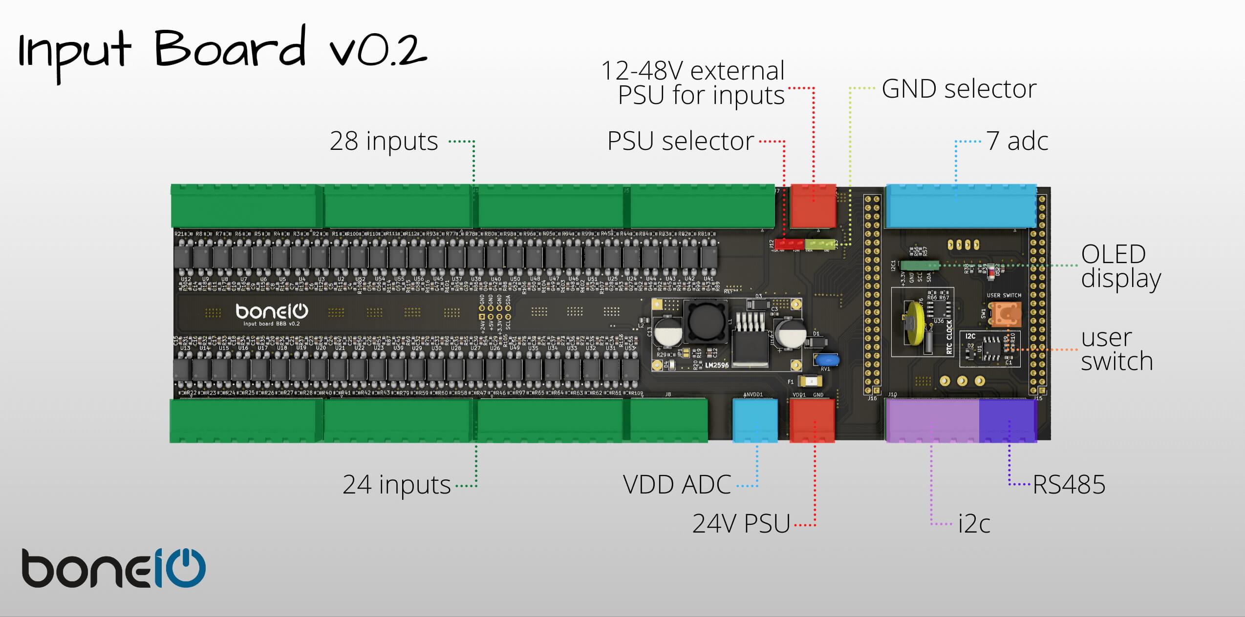
Specification
- 52 Digital Inputs
- 7 ADC
- i2c
- rs485
- RTC
- OLED Display
- Button
Bill of Materials
Here you will find complete BOM soon ;)
Assembling components
Buck converter
If you use buck converter module instead of soldering single parts on the Input Board, you have to set the 5V voltage before you solder the module on the board. The default voltage of the module is about 20V so if you forgot about this step you will damage your Input Board.
OLED Display
boneIO uses 1.3" OLED Display to show some config data of the controller such as IP address, cpu and memory utilization and states of relays. To assemble the screen you have to buy proper one at first. The screen occurs with two different pinouts and you need one that has pinout like in the picture below.
(VCC, GND, SCK, SDA)
You have also replace the male connector (which is soldered to the display by default) with female connector. You will need standard female connector - 4 pins, raster 2.54.
RS485 Module
To use RS485 interface in boneIO you have to add RS485 module to your controler. We use UART to RS485 converter like you see on picture below. This module uses only two GPIO pins on BBB.
Unlinke Buck Converter you cannot choose if you want to solder from parts. In this case you have to solder whole module, and it's being mounted on the back side of the Input Board like in picture below.